
Simple series and parallel circuits feel manageable, but the moment a circuit has multiple loops and multiple batteries, most students freeze — it’s no longer obvious which direction current flows, or which equations to even write down. Kirchhoff’s laws are the systematic tool that solves this, but the process of setting up the equations (not just knowing the laws exist) is where assignments are actually won or lost. This guide walks through both laws individually, then works through a full multi-loop circuit from start to finish.
Table of Contents
ToggleKirchhoff’s Two Laws, Precisely Stated
Kirchhoff’s Current Law (KCL): The sum of currents entering a junction equals the sum of currents leaving it. This is simply a statement of charge conservation — charge can’t pile up or disappear at a junction.
Kirchhoff’s Voltage Law (KVL): The sum of voltage changes around any closed loop in a circuit equals zero — conceptually the electrical version of the conservation of energy principle applied to a charge traveling around a complete loop and returning to its starting point with no net change in potential energy.
Setting Up a Circuit Problem: The Method
- Label every current in the circuit with a symbol (I₁, I₂, I₃…) and an assumed direction (an arrow). If you guess the direction wrong, the math will simply give you a negative value for that current — this is completely fine and doesn’t mean you made an error.
- Apply KCL at junctions where currents split or combine, writing one equation per independent junction.
- Apply KVL around loops, choosing a direction to “walk” around each loop and tracking voltage rises and drops as you cross each component.
- Sign convention for KVL: When walking through a resistor in the same direction as your assumed current, the voltage drops (subtract IR). When walking through a battery from − to + terminal, the voltage rises (add EMF); from + to − terminal, it drops (subtract EMF).
- Solve the resulting system of equations simultaneously.
Worked Example 1: Single-Loop Circuit (Building the Method)
Problem: A single loop contains a 12V battery and two resistors in series, R₁ = 4Ω and R₂ = 8Ω. Find the current in the circuit.
Step 1 — Label current: Assume current I flows clockwise.
Step 2 — Apply KVL, walking clockwise starting just after the battery’s negative terminal: +12 − I(4) − I(8) = 0
Step 3 — Solve: 12 = 12I I = 1 A
Answer: The current is 1 A, flowing in the assumed clockwise direction (positive result confirms the assumed direction was correct).
Common mistake to avoid: Getting the sign of the battery term wrong. Walking from the − to + terminal of a battery is a voltage rise (positive in the equation); walking the other way is a voltage drop (negative). Getting this reversed is the single most common sign error in single-loop KVL problems.
Worked Example 2: Two-Loop Circuit (Full Kirchhoff’s Laws Application)
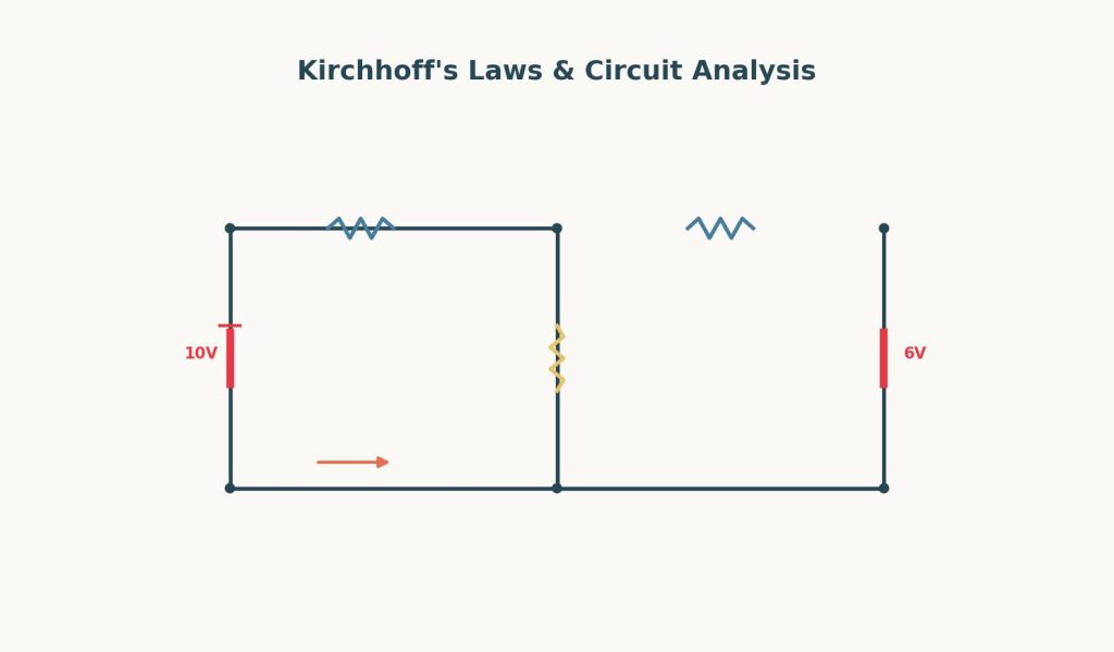
Problem: A circuit has two loops sharing a middle branch. The left loop contains a 10V battery and resistor R₁ = 2Ω. The right loop contains a 6V battery and resistor R₂ = 3Ω. The shared middle branch contains resistor R₃ = 5Ω. Find the current through each resistor.
Step 1 — Label currents: Let I₁ flow through R₁ (left loop, clockwise), I₂ flow through R₂ (right loop, clockwise), and I₃ flow through R₃ (the shared middle branch, assumed downward).
Step 2 — Apply KCL at the top junction (where the three branches meet): I₁ = I₂ + I₃ … (Equation 1)
(This assumes I₁ flows into the junction, and both I₂ and I₃ flow out — the specific assumed directions depend on the circuit diagram, but the key skill is writing one KCL equation per independent junction.)
Step 3 — Apply KVL to the left loop (walking clockwise: through the 10V battery from − to + is a rise, through R₁ is a drop, through R₃ is a drop since I₃ flows in the same direction as our walk): 10 − I₁(2) − I₃(5) = 0 … (Equation 2)
Step 4 — Apply KVL to the right loop (walking clockwise: through R₃ against the assumed I₃ direction is a rise, through R₂ is a drop, through the 6V battery from + to − is a drop): −I₃(5)(−1) − I₂(3) − 6 = 0, which simplifies to: 5I₃ − 3I₂ − 6 = 0 … (Equation 3)
Step 5 — Substitute Equation 1 (I₁ = I₂ + I₃) into Equation 2: 10 − (I₂ + I₃)(2) − 5I₃ = 0 10 − 2I₂ − 2I₃ − 5I₃ = 0 10 − 2I₂ − 7I₃ = 0 … (Equation 2, revised)
Step 6 — Now solve Equations 2 (revised) and 3 simultaneously.
From Equation 3: 5I₃ − 3I₂ = 6, so I₂ = (5I₃ − 6)/3
Substituting into Equation 2 (revised): 10 − 2[(5I₃ − 6)/3] − 7I₃ = 0 Multiply through by 3: 30 − 2(5I₃ − 6) − 21I₃ = 0 30 − 10I₃ + 12 − 21I₃ = 0 42 − 31I₃ = 0 I₃ = 42/31 ≈ 1.35 A
Step 7 — Back-substitute to find I₂ and I₁: I₂ = (5(1.35) − 6)/3 = (6.75 − 6)/3 = 0.75/3 = 0.25 A I₁ = I₂ + I₃ = 0.25 + 1.35 = 1.60 A
Answer: I₁ ≈ 1.60 A, I₂ ≈ 0.25 A, I₃ ≈ 1.35 A.
Common mistake to avoid: Trying to solve all three equations independently without substitution. Multi-loop circuits always produce a system of simultaneous equations — the practical skill being tested is careful algebraic substitution to reduce three unknowns down to one, not any new physics concept beyond the two laws themselves.
Worked Example 3: Resistors in Series and Parallel (A Shortcut Before Reaching for Kirchhoff’s Laws)
Before applying Kirchhoff’s laws to a complex circuit, it’s often worth checking whether parts of it can be simplified using series/parallel combination rules first — this can turn a multi-loop problem into a much simpler single-loop one.
Series resistors: R_total = R₁ + R₂ + R₃ + … Parallel resistors: 1/R_total = 1/R₁ + 1/R₂ + 1/R₃ + …
Problem: A 20Ω resistor is in parallel with a 30Ω resistor, and this combination is in series with a 5Ω resistor, all connected to a 24V battery. Find the total current supplied by the battery.
Step 1 — Combine the parallel resistors: 1/R_parallel = 1/20 + 1/30 = 3/60 + 2/60 = 5/60 R_parallel = 60/5 = 12Ω
Step 2 — Add the series resistor: R_total = 12 + 5 = 17Ω
Step 3 — Apply Ohm’s Law: I = V/R = 24/17 ≈ 1.41 A
Answer: The battery supplies approximately 1.41 A.
Common mistake to avoid: Applying the series formula to resistors that are actually in parallel, or vice versa. A quick way to check: resistors are in parallel if both ends of each resistor connect to the same two nodes (same two points in the circuit); they’re in series if they share only one common node with no other branch connecting there.
When Series/Parallel Shortcuts Don’t Work — And Kirchhoff’s Laws Are Required
Series/parallel simplification only works when resistors can be cleanly identified as sharing common nodes in a simple way. Circuits with multiple independent EMF sources (like the two-battery example above), or resistor networks that don’t reduce cleanly (such as a Wheatstone bridge configuration), require the full Kirchhoff’s laws approach shown in Worked Example 2, since there’s no way to combine them using simple series/parallel rules alone.
A Step-by-Step Checklist for Students Stuck on a Kirchhoff’s Laws Problem
- First check whether series/parallel combination rules can simplify part of the circuit — this can save significant time before resorting to the full Kirchhoff’s laws method.
- Label every unknown current with a symbol and an assumed direction — a wrong guess just produces a negative answer, which is fine.
- Write one KCL equation for each independent junction (a circuit with J junctions typically needs J − 1 independent KCL equations).
- Write one KVL equation per independent loop, carefully tracking the sign convention: drops when walking through a resistor in the same direction as assumed current, rises when walking through a battery from − to + terminal.
- Use substitution to reduce the system of equations to one variable at a time, solving step by step rather than trying to solve everything simultaneously in one pass.
Kirchhoff’s laws become especially challenging when a full assignment combines circuit analysis with Ohm’s law, electrical power, and experimental data. For students working through broader circuit-analysis coursework, our Physics Assignment Help service provides support across these physics topics.
FAQs
Q1: What happens if I guess the wrong direction for a current? Nothing goes wrong with your method — if your assumed direction is incorrect, solving the equations will simply produce a negative value for that current, which tells you the actual current flows opposite to your assumed direction. The magnitude will still be correct as long as your equations were set up consistently.
Q2: How many KVL and KCL equations do I need for a given circuit? As a general rule, you need enough independent equations to match the number of unknown currents. For a circuit with J junctions and B independent loops, you’ll typically use (J − 1) independent KCL equations and enough KVL equations (one per independent loop) to reach the total number of unknowns.
Q3: Why do I sometimes get a negative resistor voltage in my KVL equation? This happens naturally depending on which direction you’re “walking” around the loop relative to the assumed current direction through that resistor — walking in the same direction as the assumed current gives a voltage drop (negative in the sum), while walking against it gives a voltage rise (positive). This is a normal part of the sign convention, not an error.
Q4: When should I use series/parallel simplification instead of full Kirchhoff’s laws? Use series/parallel simplification whenever a circuit contains only resistors that can be clearly grouped as sharing common nodes in a simple pattern, and there’s only one EMF source (or sources that can be combined similarly). Once a circuit has multiple independent EMF sources or a more complex resistor network (like a bridge configuration), the full Kirchhoff’s laws method is necessary.
Q5: Is there a way to check my answer after solving a multi-loop circuit? Yes — substitute your solved current values back into all of the original KCL and KVL equations (not just the ones you used last) to confirm they all balance to zero or hold true. You can also do a quick sanity check using conservation of energy: the total power delivered by all batteries should equal the total power dissipated across all resistors.
Q6: How does this connect to other assignment work? Setting up and solving simultaneous equations here uses the same systematic, one-equation-per-unknown discipline as the free-body diagram method in Newton’s Laws of Motion. If your circuit lab asks you to compare a measured current to a predicted one, reporting that comparison properly means applying the percent-error and propagation methods from Error Analysis and Uncertainty in Physics Lab Reports.